


Compare Objects
Performing a freestyle cut
Learn how to perform your own cut pattern by hand.
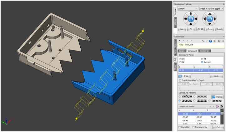
- Select your object and open the cut tool (Tools | Cut)
- Click on the [Compound] tab panel within the active task panel.
- Select the Plane you wish to perform the cut on:
- XY: the Z axis
- YZ: the X axis
- XZ: the Y axis
- Current: no axis change
- Select “Freestyle” cut pattern
- Drag the ball marker to your desired starting point (left click+drag on the line between balls).
- Drag the yellow ball markers through the selected object, dragging and releasing the yellow balls until you have your desired cut pattern.
- Press the [Cut] button to perform the cut.
(To set the cut plane along your current view simply press the button).
Note: A cut cannot be performed on an object unless it is selected (left click on an object to select it).
Editing a compound cut
Learn how to undo or edit a cut pattern.
- Left click on a ball marker to select the pattern (it will turn light blue).
- To remove a ball simply left click on the ball you wish to remove and click the “Delete point” button in the task panel.
- To insert a ball simply left click on the “Insert point” button in the task panel to add a ball marker in front of your currently selected ball marker.
- To change the dimensions of a pattern click on the button and edit the A and B parameters to increase or decrease the size of the pattern:
- To rotate a cut pattern (90 degrees clock-wise) simply click on the rotate icon:
- To close a pattern simply click on the close polyline icon:
Note: A cut cannot be performed on an object unless it is selected (left click on the object to select it).
Altering the depth of a cut
Learn how to create a cut with variable depth.
- 1. In the [Compound] cut panel select the “Enable Variable Cut Depth” checkbox.
- 2. Use the left and right sliders to adjust the top and bottom of the cut depth.
- 3. To see the cut depth lines simply rotate your view (right click+drag in the model space) and observe the dotted lines protruding on both sides of the pattern line.
- 4. To see inside the object check the transparency checkbox and the object transparency will be set to 25% allowing for easy inside and outside shell identification.
Note: To perform a depth cut the dotted lines must always go through two walls; the inside and outside of a shell.
If you have suggestions for future Tech Tips, please email us at support@solidview.com.